
 Online Service
 Top
Top
 Service
 Feedback
 You May Like

Product details

Introduction
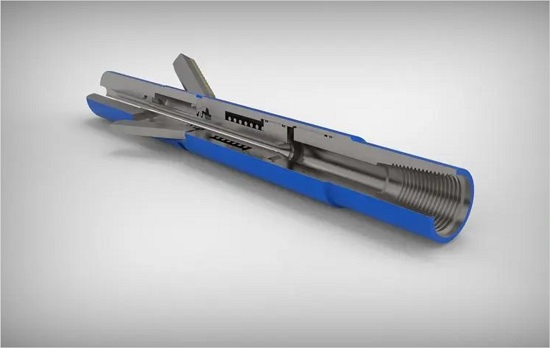
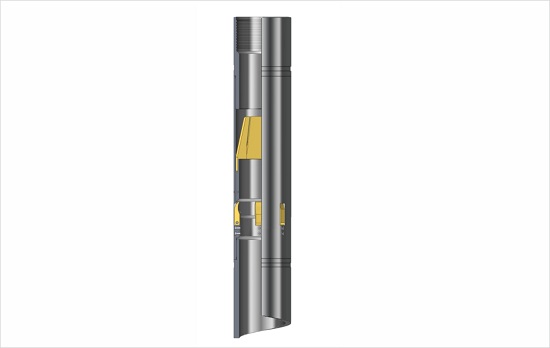
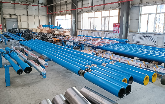
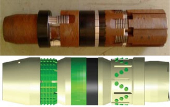
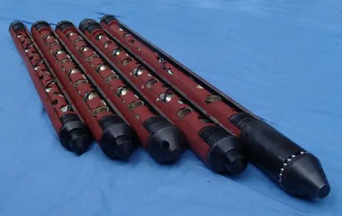
heavy duty hydraulic disconnect allows coiled tubing downhole tool string to disconnect tools by dropping a ball under certain conditions. The release/connection mechanism of heavy-duty hydraulic disconnect adopts the design of enveloping block, which makes it have the characteristics of high strength, impact resistance and fatigue load compared with other designs. Arc-shaped fitting anti-torque tooth design makes heavy duty hydraulic release high anti-torque, which is very suitable for heavy duty coiled tubing drilling and milling operations.
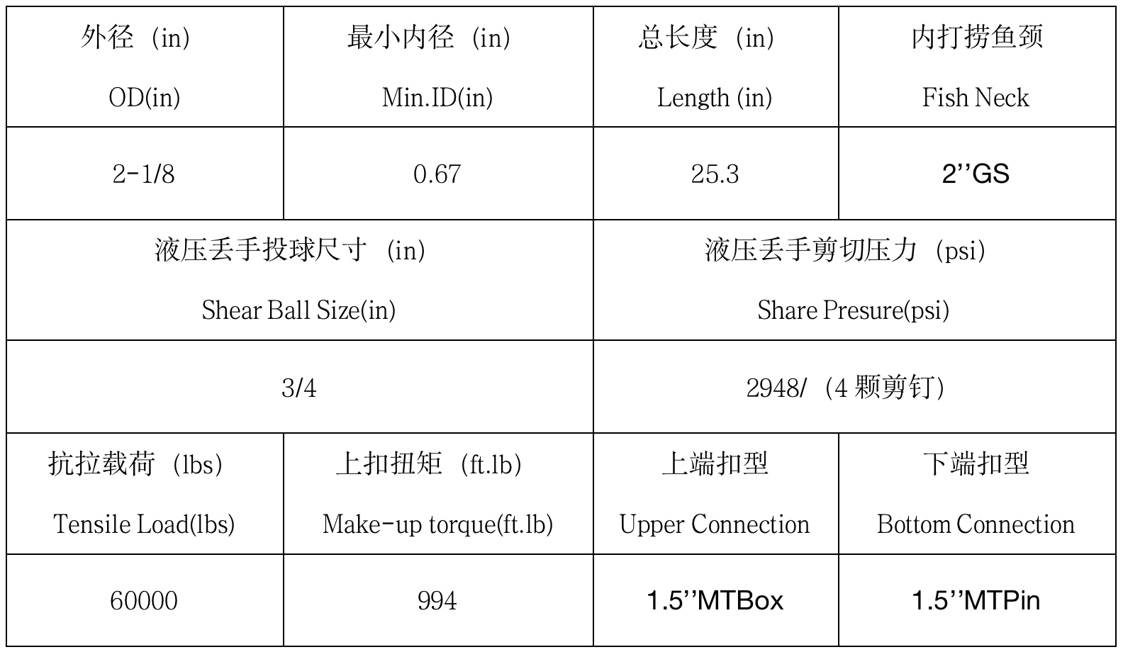
Heavy duty hydraulic release piston pressure self-balance, only be disconnected after drop a ball and increase pressure to shear pins, the release pressure can be adjusted by changing the number of shear pins installed. In addition, the heavy duty hydraulic release of the large diameter through the replacement of different diameter/seat piston, thereby changing the size of the ball. For example, in some operations, the hydraulic release is connected to the lower end of the jar and accelerator in order to retrieve as many tool strings as possible after the release of the hydraulic release. Due to the limitation of jar/accelerator inner diameter, the ball size is small. By changing piston with different inner diameter, hydraulic pressure disconnect of the same specification can meet different operation requirements.
Standard "GS" internal fishing neck is left after heavy duty hydraulic disconnect released which is fit standard "GS" fishing spear for fishing operation.
Characteristics
Specification
Maintenance
Assembly Procedure
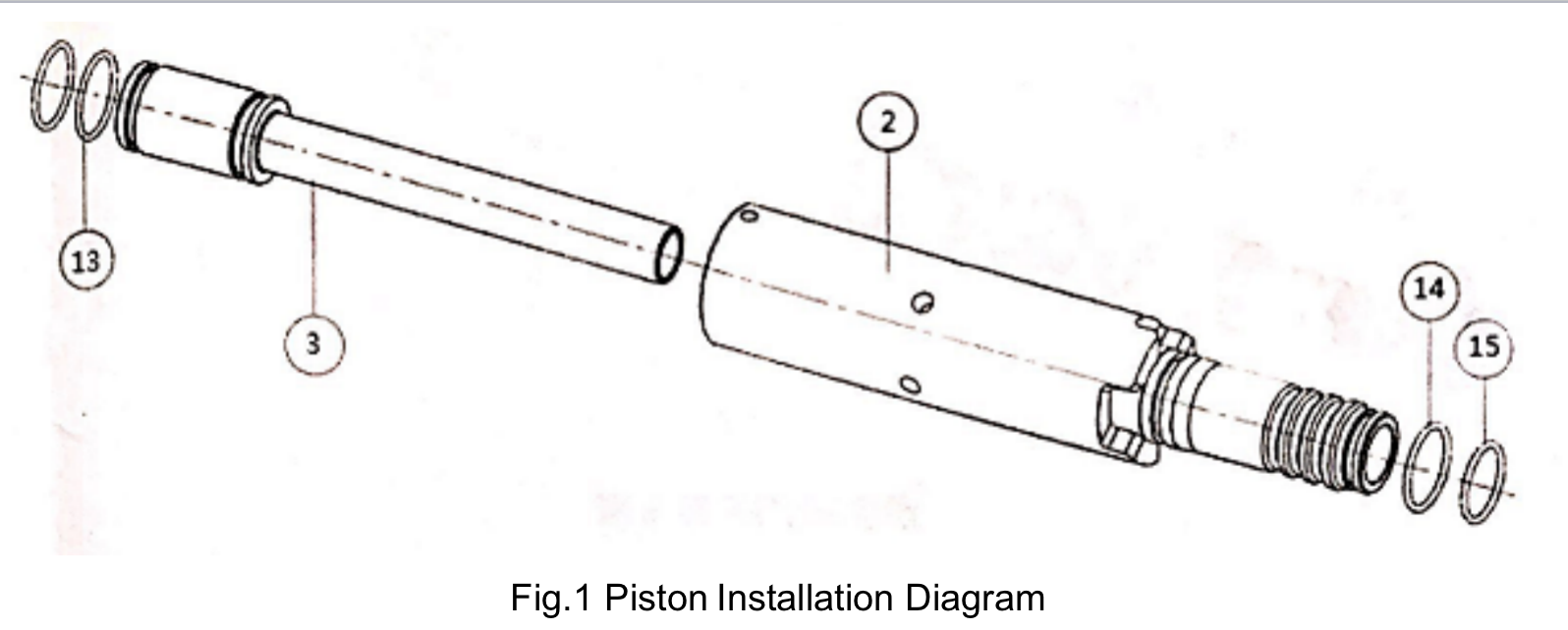
1、Install 2 O-rings(13) to piston(3) in sequence, then grease O-rings.
2、Install piston(3) in upper connecting set(2).
3、Install O-ring(14) and O-ring(15) in upper connecting set(2), install O-ring(15) at end side. Refer to fig.1.
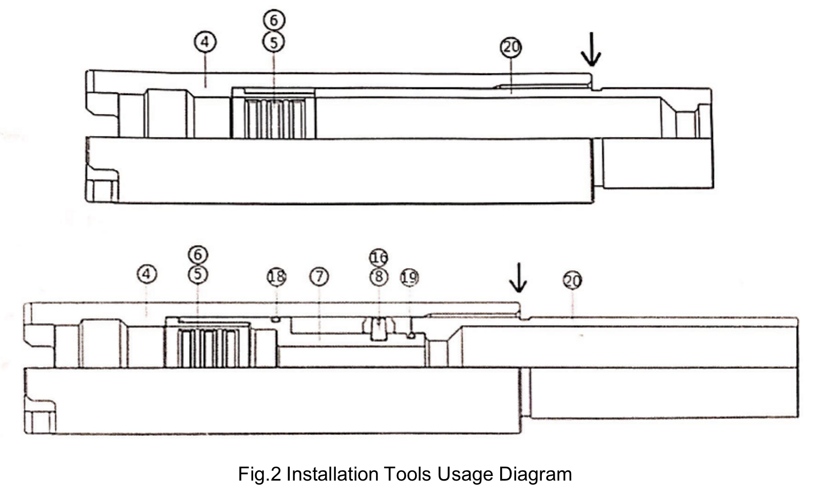
4、Install support set(5) with fixed block(6) then install with bottom connecting set(4), check and confirm all parts are installed as per design, then install tool(20). Refer to Fig.2.
5、Make up assembled upper connecting set(2) with bottom connecting set(4), adjust blocks location to ensure blocks retracted inside support set(5). Note: grease between blocks and upper connecting set will help for installation.
6、Install O-ring(18) and O-ring(19) to shear shaft(7), match holes of shear ring(8) with groove of shear shaft, then screw in 4 pieces of share pins(16), then install assembled shear shaft with bottom connecting set(4) as designed.
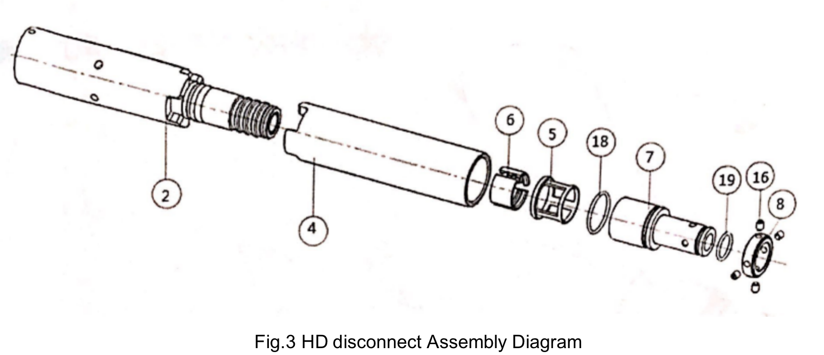
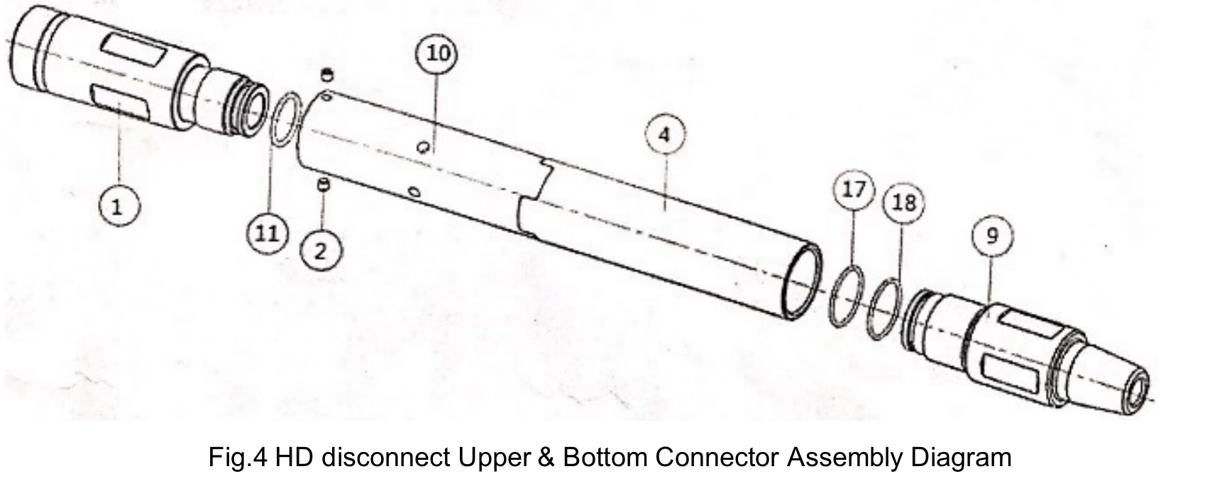
7、Install O-ring(17) at the front end of bottom connector(9), install O-ring(18) at groove of bottom connector(9), make up bottom connector (9) with bottom connecting set(4), tighten up.
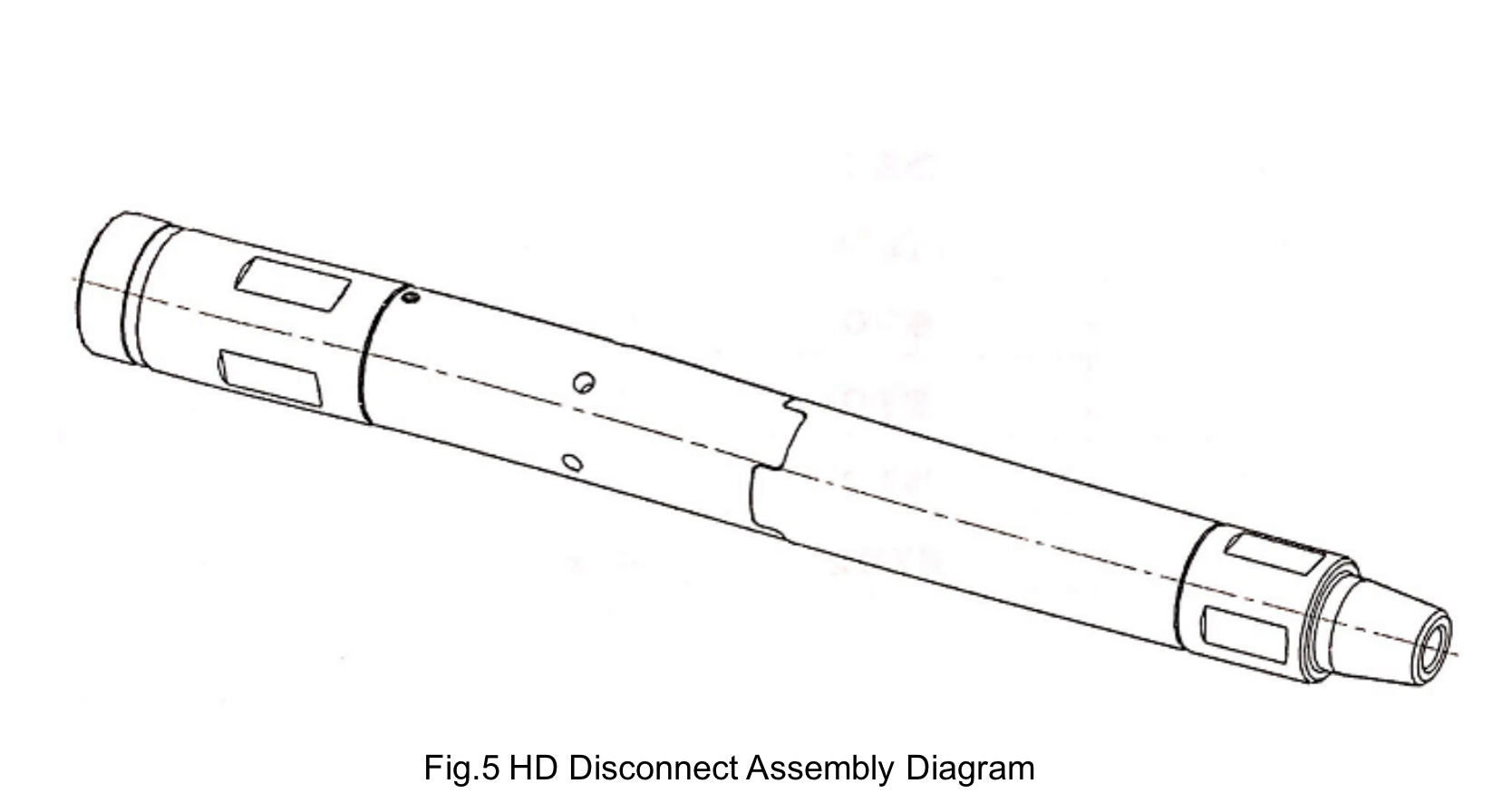
8、Install O-ring(11) in upper connector(1), grease the O-ring, make up upper connector(1) with upper connecting set(2), install 2 pieces fixed screws(19) with upper connecting set(2), tighten up screws. Refer to fig.4.
Disassembly procedures
The disassembly process is the reverse of the installation process. The disassembly can be completed by referring to the above installation process.
2-1/8” HD Disconnect Assembly Diagram


Global Hotline
+86 400-881-5588
If you have any questions, please contact the customer service email: servic@atoilgas.com
Service Time:
Monday to Friday, 10:00 to 17:00 Beijing Time
 Scan and follow us